37+ one to one relationship in er diagram
Up to 24 cash back An ER diagram or Entity Relationship Diagram ERD is a type of flowchart or graphical approach that helps you illustrate how different entities relate to each. Entity relationship diagrams in software engineering.
The Entity-Relationship Diagram ERD tool is a database design tool that provides a graphical representation of database tables columns and inter-relationships.

. Key Attribute The attribute which uniquely identifies each entity in the entity set is called key attributeFor example. ER-Diagram is a pictorial representation of data that describes how data is communicated and related to each other. Any object such as entities attributes of an entity sets of relationship.
In ER diagram attribute is represented by an oval. ERD can give sufficient. You can add a one-to-one relationship using a dedicated tool from the toolbox.
Baca Juga
Following are the main components. How to create a new one to many relationship. The equivalent relations for the above ER diagram are as follows.
Add two tables to the ER diagram. On the toolbar click the Relationship button. How to Create One to One Relationship.
ER Diagram is a visual representation of data that describes how data is related to each other using different ERD Symbols and Notations. There are several types of relationships between tables but probably the most common is the one-to-many relationship which is often written as 1N. 2 ER diagram in dbms stands for entity relationship which helps us to understand the relationship.
Here Only one table is required. An entity-relationship ER diagram can be created based on these three types which are listed below. Entity relationship diagrams are used in software engineering during the planning stages of the software project.
Then create a new relationship. Lucidchart is the leading ER diagram tool. Choose 1 to 1 button and drag it between two entities.
Eer diagram in dbms reducing er diagrams. Entity-relationship diagrams ERD are essential to modeling anything from simple to complex databases but the shapes and notations used can. In relational database design a one-to-one 11 relationship.
In the above ER-Diagram we have only one One-to-One Relationship manages We got the manages relationship from the department manager attribute of the department table. One-one many-one many-many can be done in a similar fashion.
Doctor And Patient Chen Er Diagram Data Modeling Doctor Patient
Online Shopping Er Diagram Relationship Diagram Diagram Flow Chart
Dayegram Map Map Screenshot
Entity Relationship Diagram Erd Solution Conceptdraw Com Relationship Diagram Notations Erd
Players System Er Diagram Basic Computer Programming Relationship Diagram Diagram
Er Diagram For Hotel Management System Hotel Management Relationship Diagram Diagram
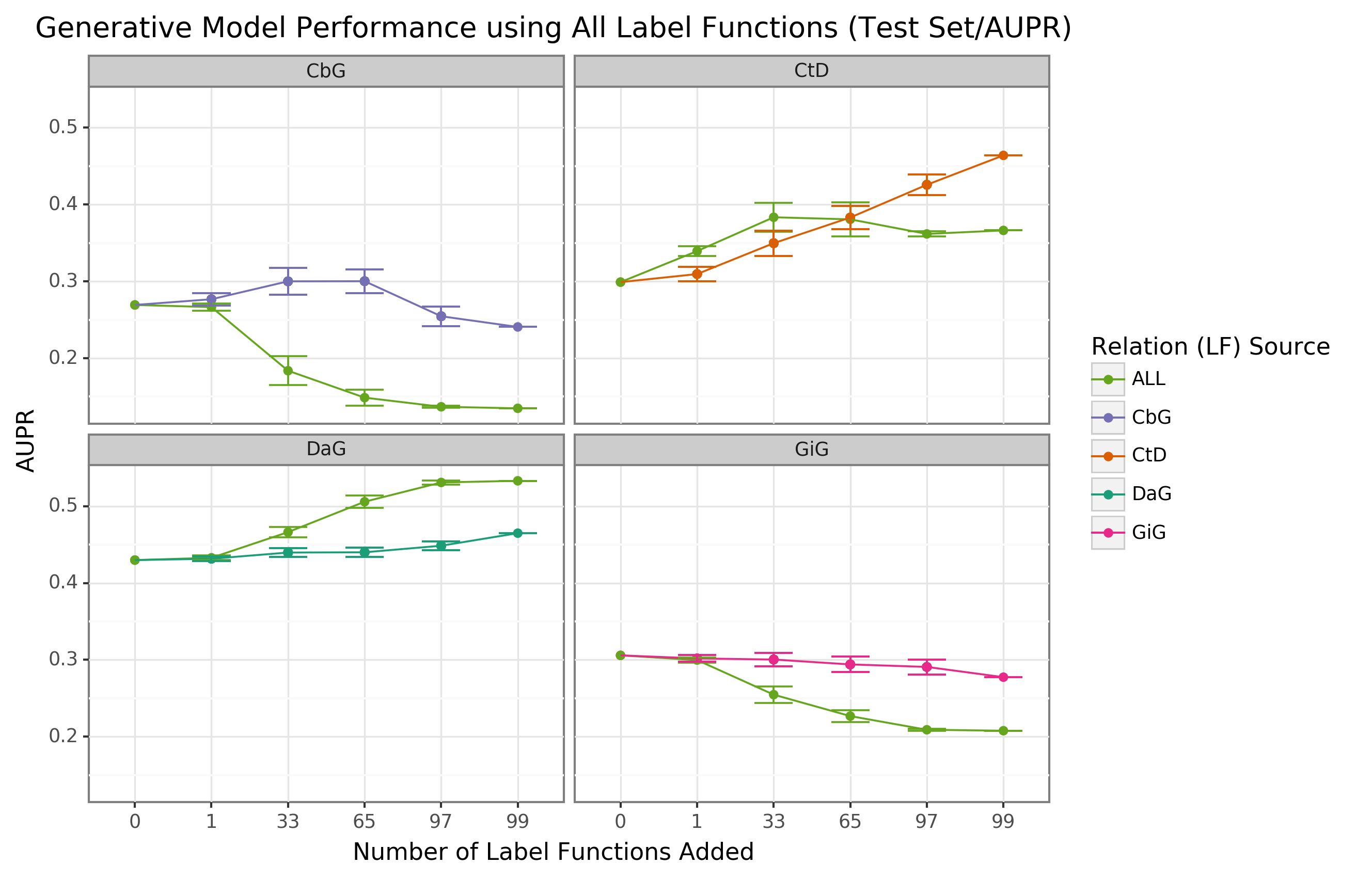
Expanding A Database Derived Biomedical Knowledge Graph Via Multi Relation Extraction From Biomedical Abstracts
Developing An Application Relationship Diagram System Architecture Diagram Database Design
Personal Coach Management Er Diagram Relationship Diagram Diagram Templates
Information Engineering Style Cardinality Erd Relationship Diagram Information Engineering Diagram
Entity Relationship Diagram Er Diagram In Dbms
How To Make Relational Model From Er Diagram Relational Model Diagram Coding
Expanding A Database Derived Biomedical Knowledge Graph Via Multi Relation Extraction From Biomedical Abstracts
Online Food Ordering System Order Food Relationship Diagram Online Food
Entity Relationship Diagram Erd Er Diagram Tutorial Relationship Diagram Diagram Data Flow Diagram
Online Album Er Diagram Relationship Diagram Online Album Diagram
Chen Notation Entity Relationship Diagram This Sample Diagram Using The Chen Notation Solution Shows The Type Of I Relationship Diagram Diagram Notations